
Page 214 - Kỷ yếu hội thảo quốc tế: Ứng dụng công nghệ mới trong công trình xanh - lần thứ 9 (ATiGB 2024)
P. 214
th
HỘI THẢO QUỐC TẾ ATiGB LẦN THỨ CHÍN - The 9 ATiGB 2024 207
aluminum quickly, which results in the creation of a 5 At the ingates, the mold
fine grain structure. [5], [6], [7] metal is significantly worn
and cracks are created.
Mold cavities are normally heat-treated by
quenching which can help them enduring high
pressurized heated melting metal flow, for example,
cavity made of SKD61 is quenched and reached at 6 The corners of the
level of Rockwell Hardness over 50 units. Due to negative side of casted part
hardness reducing at point A2 and A3, which are are worn, creating cracks
ingates where high pressurized heated melting met-al and tend to pile up the
flow into the cavity and cause die wear (see figure 1) metal.
[3], [4]
7 The surface of the cavity is
deformed due to the
erosion of hot metal flow
and causing cracks.
8 The corners of both ends
of the negative part are
eroded and the cast metal
spills over and is still
remained
Measured points by Rockwell Hardness testing, on the mold plate.
scale C A1 54.2, 53.4, 53.5 HRC 9 The curved facial
A2 50.8, 52.3, 52.4 HRC features are deformed
A3 53.1, 49.4, 53.9 HRC
A4 53.7, 53.8, 54 HRC
Fig. 1. Cavity, made from SKD61, quenched
Table 1. Common failures on Die wear and cracks are actually most typical
surfaces of mold’s cavity used in HPDC issues concerned with productivity of the mold. The
Nr. Defects on cavity surface of die Causes and Analysis table 1 demonstrates some common failures which
1 Square corners on the can be founded on the cavity such as cracks, erosions,
parting surface are deformation, etc. These typical failures have been
corroded into blunt analyzed in some dies for High Pressure Die Casting
rounded corners due to
hot metal fluid with high while the research has been conducted.
pressure, pushed into the The fact is that geometric changes on cavity’s
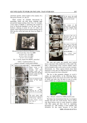
cavity via biscuit. surface are unpreventable. In the following figure,
indentations can be seen at two red circles with value
2 Cracks are appeared on the of -0.022 mm after only 50 shots in case of cavity
surface at the runner
position made of S50C due to high pressurized metal flows.
3 Runner's surface
shows cracks
following the tool path
profile left after machining
4 The metal runner walls
wear down in the direction Fig. 2. Result, scanned by CMM of mold cavity
of flow during injection
The figure has demonstrated that die wear happen
molding. Runner corners steadily and with very small amount. That is reason
also tend to
why these failures such as cracks should be welded
wear out
with filler metal and then fixed by machining
procedures [2]. TIG welding is most suitable and
affordable for this repair because of its high
ISBN: 978-604-80-9779-0